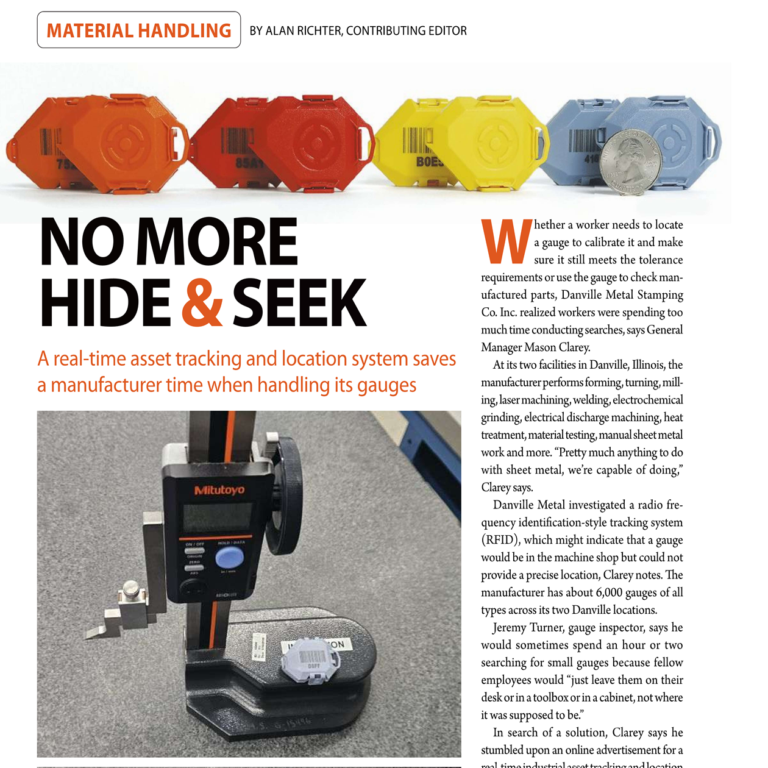
The WISER Antennas are certainly an unusual shape. But they are not (only) a work of art. At WISER, we design everything in-house, from the mounting hardware up to the analytics software. The Antenna’s design is a result of optimizing for performance while keeping the cost per Antenna low. So while customers can install and then safely forget these Antennas, I wanted to share some of the considerations that go into their design and installation.

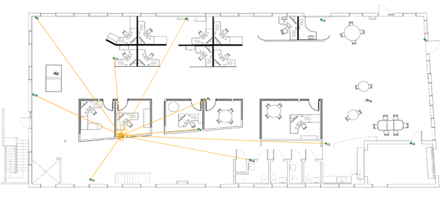
A little background first. Stationary WISER Antennas are placed around a facility to create a wireless mesh in which objects can be tracked. Somewhat like GPS satellites, they triangulate the position of mobile tags, and accuracy improves the more WISER Antennas that are within range. We call these devices “Antennas” to communicate their purpose. For this article, I will try to use a capitol letter for WISER Antennas to avoid confusion with the literal radio antennas discussed.
Designed with Easy Installation and Calibration in Mind
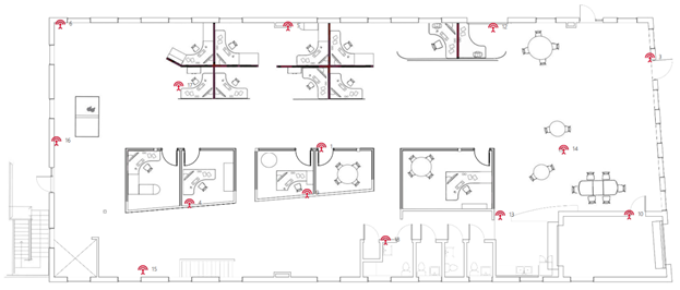
Installing the system for the first time is surprisingly easy because the exact placement of WISER Antennas is not critical. If a facility is dense with equipment and walls that attenuate the signal, or the tags are partially blocked by the objects they are tracking, Antennas should be spaced closer together to increase the number potentially in range. In open facilities and outdoors, with the open sight lines of paved lots and fields, we can place Antennas much farther apart. Each Antenna can be at a different height, although mounting higher allows for better clearance over obstacles. What an installer does need to consider is that each Antenna should be able to communicate with a few others, preferably with line-of-sight, and that the Antenna’s mounted orientation is important.
Antennas that Automatically Calibrate
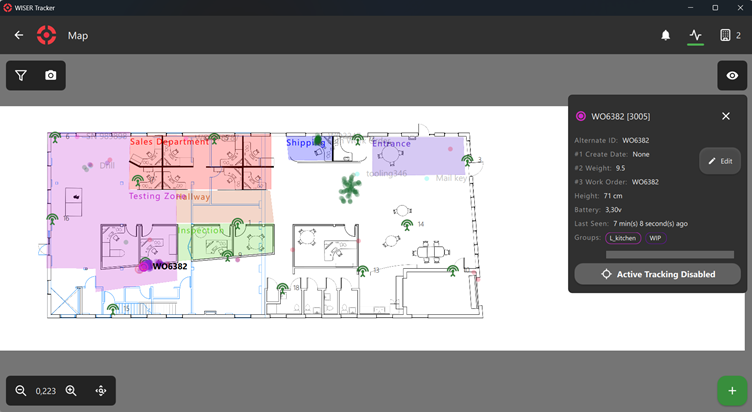
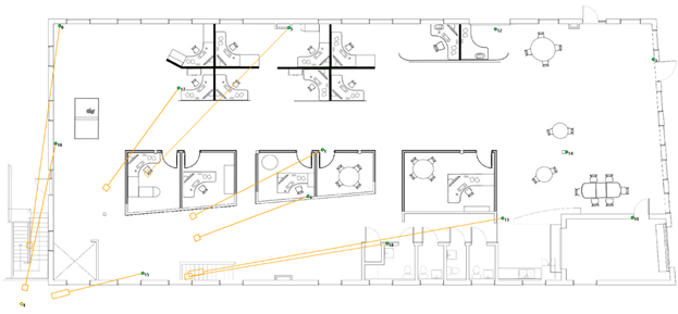
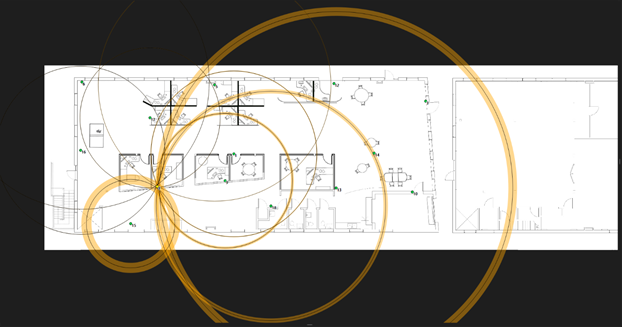
To locate tracked tags, though, we first need to know where the WISER Antennas are. Here the Antennas have a magic trick up their sleeves; they automatically build their own map of where they are through a patented automatic calibration process. Each Antenna can measure the distance to its neighboring Antennas with the same mechanism used to locate tags. If each Antenna can communicate with enough neighbors, there is only one map in which all the distances can agree.
The WISER Antenna-to-WISER Antenna communication required by this feature creates some design requirements for the Antenna’s antenna. But the design first begins, like all radio devices, with government regulations. The FCC in the US and ETSI in Europe limit Ultra-wideband to -41.3 dBm / MHz (and regulations in most other countries follow suit). That is a limit on EIRP, or Effective Isotropic Radiated Power, which limits the maximum power an antenna can radiate in any specific direction.
To communicate with all neighbors wherever they may be at the maximum distance, we would like the antenna to transmit at the legal limit in all directions. Unfortunately, just like perpetual motion machines and single-sided magnets, there is no such thing as an antenna that works in every direction (called an isotropic antenna), so compromises must be made.
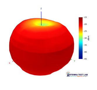
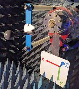
The next best choice is an omnidirectional antenna, where “omnidirectional” means coverage in every direction in a plane, but not vertically. Like the shape of an apple. This is not the whole story, as these radio waves are also polarized, so if two WISER Antennas are oriented at 90° to each other, cross-polarization loss reduces range. So while the WISER Antennas do need to be mounted vertically, with the flat of the enclosure roughly parallel to the floor, they can be oriented in any direction in the plane of the building.
Antenna Mount: Yes It Is Important
It would be possible to build a more complex pattern with multiple antennas, like a WiFi router, however at increased cost and complexity. It is cheaper to install the WISER Antenna correctly the first time and forget it.
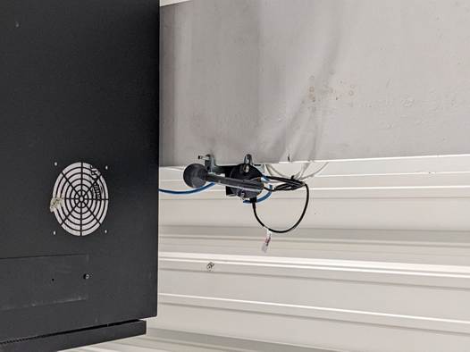
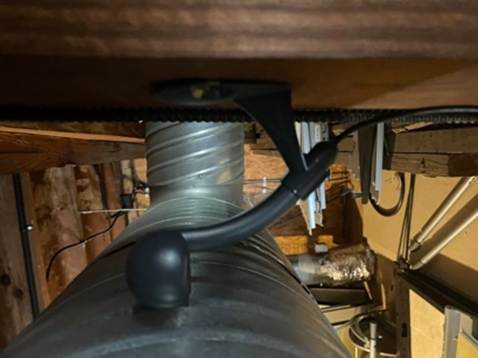
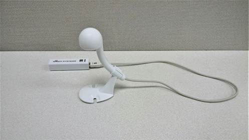
The WISER Antenna’s mounting bracket is designed to support keeping the Antenna vertical while allowing it to be mounted to a wall, ceiling, or the top of flat surface. The mount can be clipped either direction to the 45° “stem” of the Antenna. Admittedly, this is one place the Antenna’s enclosure design is lacking, as the best orientations are not necessarily obvious from looking at the enclosure. It is important to be familiar with the mounting orientations before installing a system.
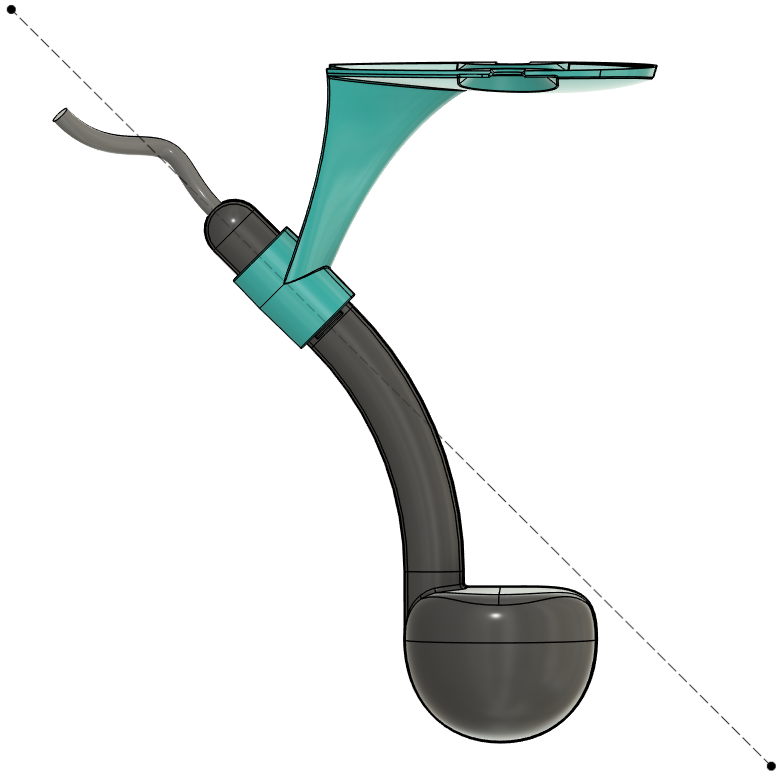
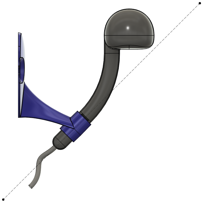
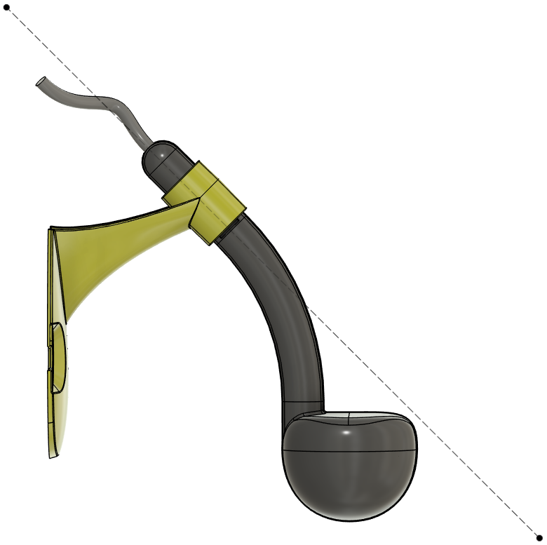
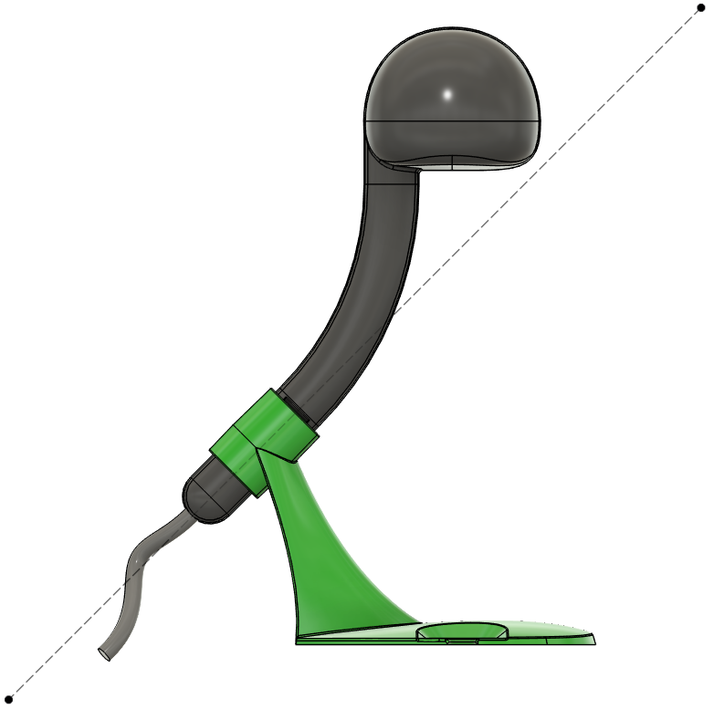
The Antenna mount and enclosure serve another important purpose; it moves the antenna away from the mounting surface. While a laser beam can travel point-to-point, lower-frequency radio waves can suffer from obstacles near their antenna and along their path. At the lowest frequency our antenna operates at of 4.5 GHz, the wavelength is roughly 2.6 inches, and the waves effectively have a “width” of a distance wider than that wavelength. Objects within one to a few wavelength distances away are in the antenna’s “near-field” and can impact the radiation pattern of the antenna. Obstacles near the path between two antennas, inside the Fresnel Zone, can also have an impact up to a larger factor of the wavelength. This is likely a gross under-simplification, but it can all be ignored by using the mounting bracket and being conscious of the “keep-out” zone around the antenna.
Flexible Power Sources
The “stem” of the WISER Antenna serves another purpose, as strain-relief for the USB cable. USB is as close to universal as any connector, providing both data and power. This means a handful of WISER Antennas can be plugged into USB battery banks, set on the tops of bookshelves ad hoc, and start tracking immediately. They can be plugged into USB power supplies and communicate wirelessly over Ultra-wideband. (A small mesh can even be set up with USB extension cables, up to twice the 22 foot cord limit, and a large USB hub. Possible, but this is definitely not recommended.) Larger meshes can use WISER’s USB-to-Ethernet adapters. And 5 Volts can be provided by solar power or other DC sources.
The end result is that WISER Antennas can be used across a wide range of applications, and a single design can be manufactured in high quantities to bring the cost down. They can be flexibly installed in any type of facility of any size and even moved as that facility evolves without lengthy recalibration. The engineering team took all of these factors into account when designing an antenna that meets the needs of our customers for high accuracy tracking in tough environments.
If you are interested in talking with someone from WISER about how we can help at your facility, please feel free to reach out. You can contact us via our website, email, or phone.